



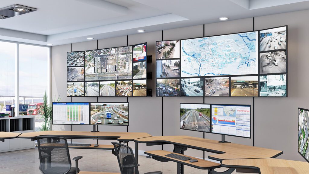
Multi-Monitor Video Walls: What to Plan Before You Mount Anything
Most multi-monitor video wall installations that look wrong weren’t let down by the displays. They were let down by the planning that happened before anything was mounted. Visible bezel gaps. Cables running across the front of the displays. Displays that can’t be read from the room’s seating positions. A wall that vibrates when someone walks past. Each of these outcomes was determined before the first anchor bolt went into the wall.
Professional video wall and multi-monitor installations — in corporate boardrooms, control rooms, broadcast environments, retail spaces, and surgical suites — have enough variables in the pre-installation phase that an experienced AV integrator or facilities manager needs a structured approach to the planning process, not just good equipment.
This article covers the pre-installation planning decisions that determine whether a video wall performs as intended: wall structure and load capacity, display size relative to viewing distance, mount type selection for the application, bezel gap management, cable management, and the thermal expansion consideration that catches most large installations off guard. The audience is AV integrators, facilities managers, IT managers, and anyone responsible for specifying or managing a professional multi-display installation.
| Quick Answer — A professional multi-monitor video wall requires six planning decisions before installation begins: wall structure and load capacity per anchor point; display size calculated from AVIXA’s viewing distance guidelines (minimum 1.5× screen height); mount type matched to the application (fixed flat, tilting, full-motion, or ultra-narrow bezel for seamless video walls); bezel gap tolerance specified to the display model’s specific bezel width; cable routing planned before mounting; and thermal expansion accommodation for large installations. The mount is the last decision, not the first. See the AFC Industries professional wall mount range for options matched to different display configurations and environments. |
What Do You Need to Know Before Installing a Multi-Monitor Video Wall?
The planning phase for a video wall installation has more variables than most buyers expect, and the cost of getting any one of them wrong after the displays are mounted is high — either the result is visibly wrong and has to be redone, or worse, it looks adequate but fails structurally over time.
The planning decisions fall into two categories: site decisions (what the room, wall, and use environment require) and configuration decisions (what the display and mount specification needs to be to meet those requirements). Site decisions always come first. Working in the opposite direction — selecting a mount or display and then assessing whether the site can accommodate it — produces a high rate of specification errors.
The table below maps the six primary planning factors against what to check for each and what failure looks like when the check is skipped. It functions as a pre-installation checklist for any professional video wall or multi-monitor installation.
| Planning Factor | What to Check | What Goes Wrong Without It |
| Wall structure and load capacity | Locate studs or solid backing; confirm wall material (drywall, concrete, steel stud); calculate total mount + display weight per anchor point | A multi-display video wall in an office with drywall and 16-inch stud spacing requires a horizontal rail system distributing load across multiple studs — not individual mounts per display anchored to a single stud |
| Viewing distance and display size | AVIXA recommends a minimum viewing distance of 1.5× the screen height for detailed content; use the room’s seating layout to determine minimum display size before specifying mounts | Under-sizing the display for the room’s viewing distance is the most common video wall planning error — the mount is secondary to whether the display can be read from the furthest seat |
| Bezel gap tolerance for video walls | Measure the bezel width of the specific display model; specify ultra-narrow bezel mounts with stated gap tolerance rather than standard mounts | Standard mounts allow 3–5mm variability in gap; ultra-narrow bezel mounts hold 0.5–1mm; the difference is visible at 2 metres and unacceptable in a professional installation |
| Cable routing and management | Plan cable pathways from display to signal source before mounting; conduit routing behind the wall surface is the cleanest approach; surface cable management is acceptable only if the pathway is concealed | A video wall with visible cables on the face of the display is an incomplete professional installation regardless of mount quality |
| Ambient lighting and glare | Note light sources and their position relative to the planned display location; anti-glare displays or controlled lighting are required for environments with windows or strong overhead lighting | A display mounted opposite a window will be unreadable during daylight in most office environments regardless of display brightness specification |
| Thermal expansion on large installations | Large video walls experience measurable thermal expansion in the display panels; ultra-narrow bezel mounts should accommodate this with micro-adjustment rather than rigid locking | Failure to allow for thermal expansion in large installations produces visible gap variation between panels during operation; this is a mount specification issue, not a display issue |
What Type of Wall Mount Is Right for Your Video Wall Configuration?
Mount type selection is a function of the installation’s application requirements, not a preference decision. Each mount type has a specific set of capabilities and limitations that either matches or doesn’t match the installation context.
| Mount Type | Adjustability | Best Application | Key Specification Note |
| Fixed flat mount | Permanent install; display flush to wall | Control rooms, boardrooms, retail signage, lobby displays | Highest stability; no adjustment after install; ideal where position never changes |
| Tilting mount | Vertical tilt adjustment only | Displays mounted above eye level; presentation screens; upper-row video walls | Reduces neck strain from high mounting; does not allow lateral or swivel adjustment |
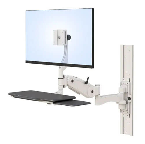
| Full-motion / articulating | Tilt, swivel, and pull-forward extension | Multi-operator control rooms; collaboration spaces; shared workstations | Maximum flexibility; heavier and more complex than fixed mounts; requires adequate wall stud or rail support |
| Ultra-narrow bezel video wall mount | Tight tolerance for bezel-to-bezel gap; precision alignment | Video wall installations; CCTV monitoring walls; broadcast production | Bezel alignment tolerance is the critical specification; ultra-narrow bezel mounts hold tighter tolerance than standard mounts under thermal load |
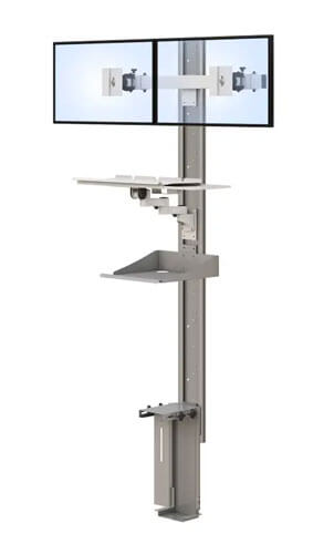
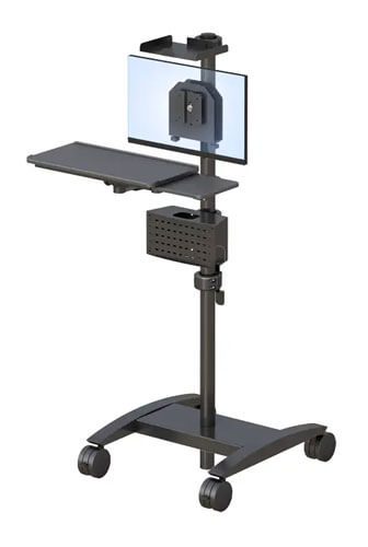
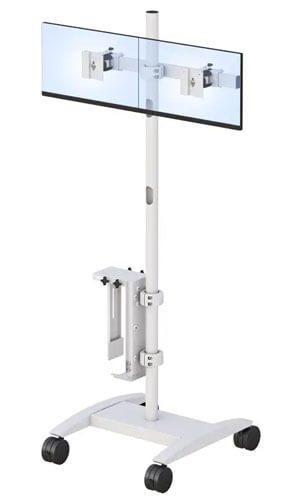
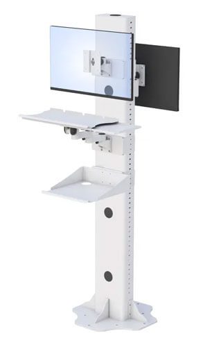
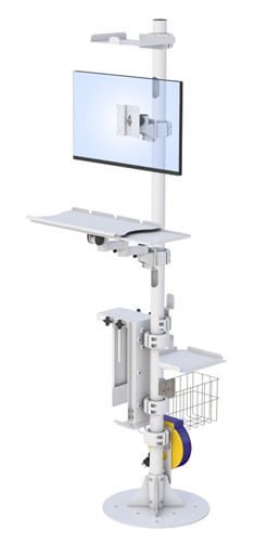
| Ceiling / pole mount | Floor-to-ceiling or ceiling-hung configuration | Open floor plans; retail; surgical suites; spaces without suitable wall space | Load rating per mounting point is the primary safety specification; seismic zone requirements apply in some regions |
For seamless video wall applications — where the goal is a near-bezel-free tiled display surface — ultra-narrow bezel mounts are not optional. A standard mount allows enough variability in panel-to-panel positioning that bezel gaps become visibly inconsistent under real-world conditions including thermal load, building movement, and the vibration from foot traffic. The gap tolerance specification — typically stated as a maximum variance in mm between adjacent panel edges — is the critical number to compare between mount options, not the price.
AFC Industries’ professional video wall mounts include ultra-narrow bezel configurations for seamless multi-panel installations and full-motion options for flexible collaborative environments. Contact the AFC Industries team to discuss display model specifications, wall structure, and room layout before finalising the mount selection.
How Do You Install and Configure a Multi-Monitor Video Wall Correctly?
The installation sequence matters as much as the installation quality. Doing steps out of order is the most reliable way to create problems that are expensive to correct.
| Installation Sequence for a Professional Multi-Monitor Video Wall
Step 1: Mark and verify structural anchor points. Locate all studs or backing elements. For drywall installations requiring load distribution, mark horizontal rail anchor points across the minimum number of studs required for the total display weight. Do not anchor individual mounts to single studs unless the mount is a single-display unit whose weight is within the stud’s rated capacity. Step 2: Install the mount rail or individual mount bases without displays. Use a laser level to ensure horizontal alignment across the installation width. For video walls, horizontal alignment tolerance should be within 1mm across the full width — a laser level is not optional. Verify all anchor points are torqued to specification and load-test by applying downward pressure before attaching any display. Step 3: Route all cables before mounting displays. Plan and install all signal cables, power cables, and control cables with displays not yet mounted. Cables that are routed after displays are mounted are almost always less cleanly managed, because the displays obstruct access to the wall routing path. For behind-wall routing, ensure all conduits are installed and cables pulled through before the first display is hung. Step 4: Mount displays from the bottom row upward. Starting from the bottom allows each row to rest on the row below during positioning, simplifying panel-to-panel alignment. Starting from the top requires holding each panel in position while aligning — physically harder and less precise. Step 5: Set panel-to-panel gap and alignment before tightening mounts fully. With all panels loosely mounted, adjust each panel’s horizontal and vertical position to achieve consistent gap across the full installation. For ultra-narrow bezel configurations, use feeler gauges or the mount manufacturer’s alignment tool to achieve the specified gap tolerance. Tighten mounts to final specification only after all panels are aligned. Step 6: Power on and test signal distribution before declaring installation complete. With all panels mounted and cables connected, power the full installation and verify signal at every display. Check for gap variation between panels in both cold and warm states — panels expand slightly when at operating temperature. If gap variation appears in the warm state, micro-adjust the mount positions before the next sign-off. |
What Are the Most Common Video Wall Installation Mistakes — and How Do You Avoid Them?
The failures that produce unprofessional results in video wall installations cluster around four recurring mistakes. Each is visible in the finished installation and each was preventable at the planning stage.
- Under-specifying load capacity per anchor point. The total weight of a video wall — including all displays, mounts, and brackets — divided across the number of anchor points must be within the rated capacity of each anchor. For large installations on drywall, this typically requires a horizontal rail system rather than individual mounts, because the per-mount load from individual anchoring exceeds drywall anchor capacity. The structural calculation must be done before purchase, not after the displays are on the wall.
- Poor horizontal alignment across the installation width. A laser level is not a convenience; it’s the only tool that reliably achieves sub-millimetre horizontal alignment across 3 or 4 metres of wall. String lines and spirit levels accumulate too much error across large widths. The result of misalignment is a video wall that looks tilted or where panels at different heights create a visible step in the bezel lines.
- Incorrect cable length planning. Cables that are too short create tension at connectors, which loosens over time and produces intermittent signal loss. Cables that are too long create excess that must be managed somewhere, which usually means coils hidden behind the installation that create heat and signal degradation in long HDMI or DisplayPort runs. The correct approach: measure every cable run to the specific connector position on the specific display model, add 10% for routing tolerance, and specify exactly.
- No allowance for thermal expansion in large installations. Display panels expand measurably when at operating temperature. In an 8-panel or larger video wall, this expansion is cumulative across the installation width and height. Ultra-narrow bezel mounts from professional-grade suppliers accommodate this with micro-adjustment mechanisms. Standard consumer-grade mounts lock panels rigidly, causing gap variation in the warm state that is not correctable without re-mounting.
The Single Most Important Principle for Video Wall Installations
Every professional video wall installation comes down to one principle: the planning phase determines the outcome. Not the display quality. Not the mount price. Not the installer’s skill on installation day. If the wall structure hasn’t been assessed, the viewing distance hasn’t determined the display size, and the cable routing hasn’t been designed before anything is mounted, no amount of installation skill corrects for those omissions.
The checklist in this article — wall structure, viewing distance, mount type, bezel gap tolerance, cable management, thermal expansion — is not a comprehensive AV engineering guide. It is the minimum set of decisions that need to be made before a professional installation begins. Each item on the checklist represents a category of failure that appears in completed installations where that item was skipped.
For organisations planning a multi-monitor or video wall installation, AFC Industries’ professional wall mount range covers fixed, tilting, full-motion, and ultra-narrow bezel configurations for corporate, broadcast, control room, and healthcare environments. Contact the AFC Industries team with your display model, room dimensions, and wall structure to discuss the right mount specification before the planning phase begins.